Toyota Turkey towards zero discharge in painting shops
In 2004 Toyota, Adapazari (Turkye) site, contacted Hydro Italia, a wellknown Italian company operating in the automotive industry. Hydro Italia is particularly appreciated for its innovations in the field of waste waters coming from spray booth.Thanks to a whole range of special systems allowing to constantly segregate denatured paint from water, Hydro Italia is capable of ensuring full recovery of water coming from spray booths, thus obtaining the continuous flowing of the water wall. The following aims should be achieved :
- suppress the need to change water in the pit ;
- obtain sludge with dry residue ranging from 50% to 70% ;
- limit the concentration of solvents and noxious substances to be found in air emissions, thanks to a more efficient of the water wall ;
- reduce the cabin maintenance costs up to 90%, avoiding the formation of scales and waste sludge.
Technical data
Solvent paint data| Paint | Overspray |
|---|---|
| Primer | 27 kg/h |
| Base coat | 27 kg/h |
| Clear coat | 27 kg/h |
Treatment data
- Volume of water in the tank after making the recommended modifications : 50 m3
- Overspray quantity :approx. 81 kg/h
- Hours of work : 20h/24h
- Plant delivery :min. 24 m3/h
Denaturation
The first step of the treatment consists in a very quick denaturation process of the small paint particles (“overspray”) captured by the water wall. Denaturation consists in transforming sticking and colouring paint into inert particles, similar to moist sand.This aims at preventing pipes and pumps from being clogged and at avoiding the formation of scales, although denatured paint particles drop in the water wall.To obtain this type of reaction, Hydro Italia use a suitable product - in this case in cooperation with Henkel Germany - which will be completely mixed with water. This is the reason why the specialist changed the tank configuration and installed submerged mixers. Because the tank volume was limited from 70 m3 to approx. 50 m3, he installed a Hydrofloty 24M plant ensuring a min. delivery of 24 m3/h and capable of changing the entire amount of water in the pit every two hours.Sludge continuous drainage and particle separation
The second step consists in separeting the denatured particles, which are transformed into large flakes that can easily float.The water to be treated is continuously taken from the tank located underneath the cabins. Water is delivered to the treating plant by a special pump: flow is adjusted by means of a safety valve. The safety valve is controlled by a level gauge (10) located inside the re-delivery tank; if the water level in the tank remarkably increases due to whatever reason, the safety valve will stop pumping. After entering the mixer (3), water is mixed with the flocculant agent held in the container (1), which is measured through the pump (2).
An agitator is installed in the tank.
The agitator keeps mixing the flocculant agent to avoid clot formation. Water/flocculant agent flow is delivered to the flotation unit through a coiled pipe. The coiled pipe is specially designed to optimize the treatment effects. Inside the tank, flowing water is enriched with minute air bubbles, which adhere to the surface of the paint particles, thus enhancing surfacing (flotation) and allowing them to be easily transferred through skimmer (6). The skimmer pushes floated sludge from the surface of the tank to the sludge collector (8). The pneumatic pump (9) takes water from the sludge collector at alternate intervals and delivers it to the re-delivery tank (10). Clarified water is then delivered to the cabin tank by means of the redelivery pump (5). The sludge thickener (11) is located on the bottom of the main tank ; it is electrically controlled and pneumatically activated. It acts as an agitator for the sludge settled on the bottom of the main tank. Particles tending to settle are retained by the pump (7) and stocked in the sludge collector (8).
Results
After installing Hydrofloty 24M, the advantages are :- no water drainage from the pit ;
- no formation of scales ;
- no sludge sediment in the cabin circuits and water walls ;
- no production halt due to hydro Italia technological process.
-
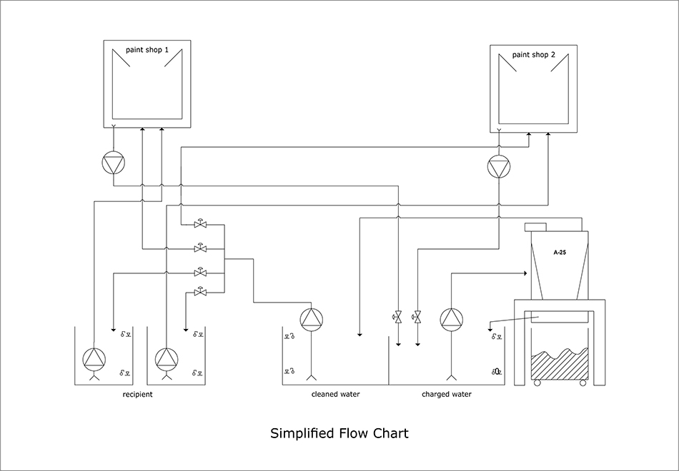
Scheme 
Technical flow - sheet Hydrofloty 24M.

Separator installation for Sludge Pit & Skimmer set-up
Existing system
One of the leading and innovative auto manufacturer has installed a separator at one of their manufacturing units.The customer has a sludge pit and skimmer system for paint sludge discharge. The paint sludge, dosed with de-tack chemical and flocculants, is continuously removed with this system. Paint sludge with approx. 70 % residual moisture is discharged every day. This sludge is incinerated in an in-house incinerator installed at the factory.
Drawbacks of existing system
- The high paint sludge quantities generated per day cannot be incinerated on same day, due to limitation of the incinerator capacity. This leads to big storage space requirement to keep the removed paint sludge for long periods.
- The open air storage/drying of paint sludge also creates foul smell and pollution in the storage area.
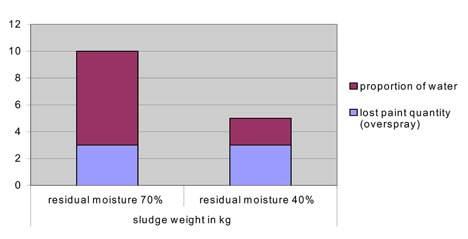
- The removed paint sludge is having nearly 70% moisture content. Hence, the paint sludge weight is quite substantial, leading to high disposal cost.
- The present sludge removal system is not able to remove some percentage of paint sludge from the sludge pit. This accumulates inside the pit, thus requiring substantial maintenance costs for pit cleaning.
- Since frequency of sludge pit cleaning is increased, the water discharge to the ETP was quite high, also causing wastage of water.
- Wastage of paint booth chemicals along with water wastage.
The expectations
The main aim was to achieve a significant reduction in the sludge disposal costs, by dewatering the sludge as well as to reduce the operating costs by savings in the water, chemical, space and labour cost. Additionally, reduction in the pollution in the specified area was of importance.
The solution
The semi-automatic paint sludge separator was selected based on sludge quantities indicated by the customer. This is a continuous type centrifuge with high cleaning/dewatering efficiency. The separator was fixed to the existing skimmer without making any major changes to the existing system. A suction device was fixed inside the skimmer and the sludge was pumped to the separator using a non-clog special pump. The clean water was routed back to the sludge pit.
In case of sludge pits without a skimmer arrangement, a specially designed Overflow Tank can be suggested for high efficiency separation and dewatering.
The results
- The separator is dewatering the paint sludge from 70% to below 30%. The overall sludge weight reduction observed was an impressive 50%.
- The water in the sludge pit/skimmer is cleaned very efficiently and effluent recycling is achieved satisfactorily, thus reducing load on ETP.
- Chemical usage is being monitored for actual savings.
- Frequency of sludge pit cleaning has reduced considerably.
- Reduction in maintenance costs of sludge pit, recirculation pumps as well as paint booths.
- Substantial savings in storage space
- Reduction in pollution in the sludge pit/storage area.
- Less contract labour required for pit and booth cleaning.
-
Scheme 
Scheme


Separator installation for “ESKA” system
An established car manufacturer generates a substantial weight of paint sludge on a daily basis. The paint sludge was being removed with the help of two separate ESKA (skimmer) systems. The removed paint sludge had a high percentage of water content, thus increasing the weight of the sludge to be disposed.Aquarius suggested 2 nos. of Automatic Sludge Separators, model A-25, one for each skimmer system. The Automatic Separator was attached to the ESKA system with a complete synchronization with the skimmer arm movement. This ensured a consistent flow of sludge to the Separator. The Separators dewater the paint sludge and bring down the water content in the sludge below 30%. This results into an overall sludge weight reduction of nearly 50%, thus slashing the disposal costs by nearly half.
Additionally, water, chemical and labor costs were reduced as well as the pollution during storage was reduced considerably.
-
Scheme 
Scheme
Separator installation without Sludge Pit
An auto component manufacturer has put up a new factory. Their major constraint is space. The paint shop consists of 3 nos. paint booths and has no sludge pit or skimmer. They wanted a system that can directly collect the sludge from the paint booths.Aquarius suggested a Semi-automatic Sludge Separator along with a special water management system. The Separator collects the sludge from the first paint booth for a specified time period. The clean water is returned to the same paint booth. After completion of the set period, the Separator automatically starts sludge collection from the second booth, with return of clean water to the second booth respectively. This cycle is continued for the third booth. After cleaning of all the 3 nos. booths, the Separator comes to a halt for the sludge removal.
The suggested system is highly efficient and can be considered while putting up of new paint shops, which will save considerable space, labor and more importantly save civil costs for installing sludge pits, etc.
-
Scheme 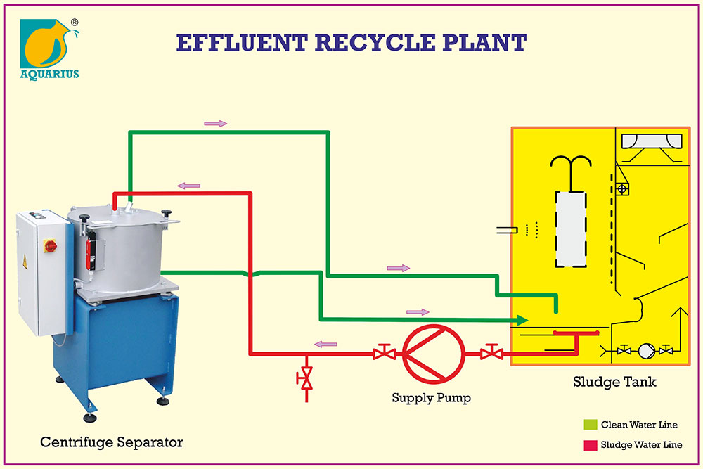
Scheme


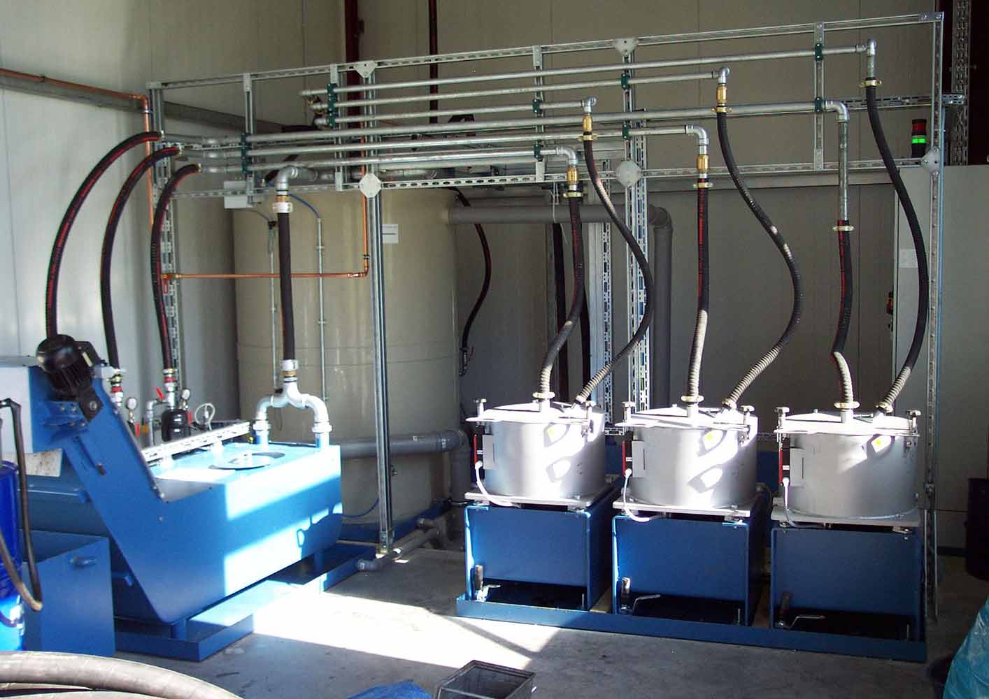
Automatic Separator installation
As one of the leading and most innovative manufacturer of high quality automobile components and operating systems for the consumer equipment industry, REUM operates with 5 automatic wet paint shops with altogether 10 paint shops for the coating of plastic parts at the locations Calw and Hardheim. Solvent and hydro paints are consumed.Reum used surface skimmers as paint sludge discharging systems. The paint, treated with coagulant for a de-bonding effect and flocculant for a floating effect on the surface, is continuously stripped of with these systems. 500 – 600 t of charged water and paint sludge with approx. 70 % residual moisture had to be discharged every year. Due to the high sludge amount and besides the costs for the discharge of the sludge, high expenditures were necessary for the stocking of the tanks as well as for the cleaning of the systems and the areas around.
The aim was on the one hand to achieve a significant reduction of operating costs by minimizing the sludge volume and by reducing personnel expenditure and on the other hand less pollution through the discharge of the paint sludge. The use of coagulant and flocculant had to be reduced and the life time of the paint shop water had to beprolonged if possible.
Solution
Altogether 4 STA Centrifugal Separators type A-25 replaced the initially installed surface skimmers gradually.2 – 3 paint shops were connected with one separator, switching in intervals of one’s choice between the paint shops.
There are 10-20 kg/h of hydro- and solvent paints used in the paint shops; approx. 50 % overspray is collected in the water. The water content per paint shop is between 1.200 l and 2.000 l. The coagulant is adjusted in a way, that hydro and solvent paints can be de-bonded and flocculated with the same product. As this coagulant does not need to float on the surface, there is no more need of flocculants.
A separate pump primes 50 l/min of the paint shop water and guides it into the separator. Therefore, it is possible to clean the paint shop water continuously in stand still periods to eliminate the last paint particles.
Pumps lead the water from the paint shop to a recipient. A perforated basket holds back greater paint cakes and tramp pieces. A feeding pump leads the liquid into the separator A-25, where it runs through the centrifugal field as shown in the scheme above. The solids, which are heavier than the liquid, stick to the drums’ side under the influence of the centrifugal acceleration of 2.000 x g.
The cleaned liquid flows back to the clean side of the recipient, therefore it is put for the process’ disposal again.
When the maximum sludge quantity is reached (adjustable time interval), the supply stops and the centrifugal basket decelerates. The remaining water escapes through centrifugal valves. The scraping mechanism is activated by a separate running and the separated paint sludge, highly compressed, falls into the container through the drum outlet at the bottom.
The centrifugal separator discharges up to 50 kg nearly dry paint sludge per hour.
A PLC controls carries out the running and the monitoring of the system. The level monitoring of the recipients and the paint shops is integrated in this control as well as the running of each paint shop per diaphragm valves. An after running time of the separator is realized by an interface to the paint shops’ PLC over the after running time of the circulation pumps.
Result
The operation with centrifugal separators reduced the residual moisture of the separated paint sludge by approx. 72%, at the same time the disposal costs per ton were reduced, as the calorific value raised.Through the easy handling of the separators and trough the reduction of the monitoring for the former surface skimmer, personnel costs were saved; furthermore the use of flocculant was no more necessary. In relation to the paint quantity used, there is approx. 16-20% coagulant used in paint shops with a combined system of solvent and hydro paints. The reduction of system failures and stand still times contributed to an amortization of the centrifuges within approx. 1 – 1,5 years.